 |
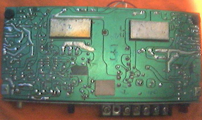
The big soldering line at bottom is there to connect the blown track. 3 pins on top of it belongs to a trimmer resistor for input level. The one next to it (right side) is the second channel, which as broken track due to improper desoldering. |
Troubleshooting
When opened up the cover, I found broken signal ground track and burn sign at the decoupling inductor (L2) between signal and power ground. Hence I soldered back the broken track and try to change the L2. However that time, there is no suitable inductor to replace, hence I just took a piece of resistor, regardless of it's value and jointed the signal and power ground. When power up, no more oscillation!!! which made myself proud until I shut down the unit, "POP" appear on my test speaker, damm.!!! I try wind up my own L2 the next day and yet got the same result, so I just changed back the old L2.
Next thing I did was dividing the power amp into three major parts, namely, power supply, pre-amp and power amp. So, what come in must come out. The pre-amp feeds audio signals to power amps, should the pre-amp generated noise or becomes oscillate, the power amp will amplifies these signals and put it to the speakers.
Firstly, isolate the pre-amp and power amp by disconnect the coupling capacitors 16V 10uF(2 channels), then measure the output of the pre-amp refer to ground using analog meter set at 10V DC scale. Result, the pulse has lesser amplitude but offset by dc component. The dc offset is due to the IC is powered by single power supply. The power section is driven by center tapped transformer, this indicate that no dc component refer to common ground should appear at the input side, however this is not true at this unit, the input stage as the same pattern of meter's needle swing as the pre-amp output before the coupling capacitor. This jump to a conclusion to replace the coupling capacitor to none polarity type, which usually has smaller value. Next thing I knew, no more strong pulse at output, what a lucky try. Final value chosen for coupling capacitors is 10nF.
Before closing up the chassis, I feed music signal to it and output from speaker is acceptable at least myself. Hiss might heard at high volume without signal, this is cause by design of the pre-amp as quote by Robert Sonthheimer, Noise: cause and remedies pg55-pg58
Apparently I took few weeks to solve the problem because a lot of misleading dead-end. The troubleshooting described above just as a summary as well as short cut. Hopefully this article will become a guideline to troubleshoot similar problem.
Picture out from cheap CCD camera
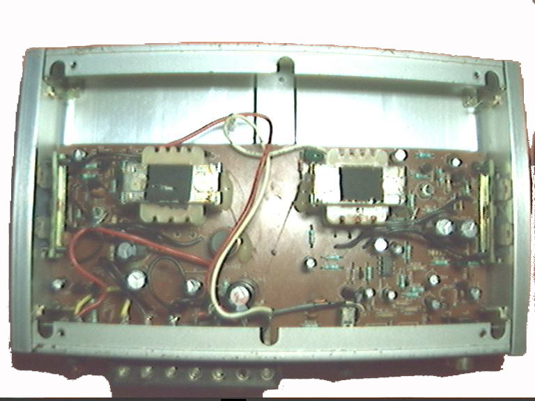
Internal top view
PCB track view
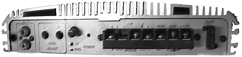
Unit's front view
Unit's top view
links to schematic diagrams, Power supply, pre-amp, power amp. COMING SOON
bubur
Reference:
| 1 | Robert Sonthheimer, "Designing Audio Circuits", Tech/Elecktor Electronic, 2001, ISBN 981-214-018-2 |